
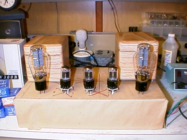
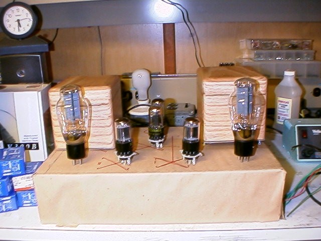
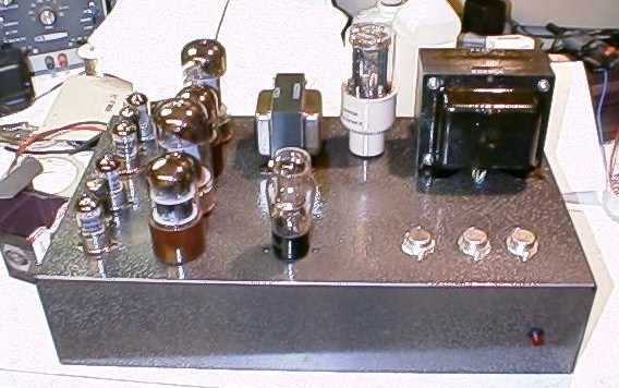
Here is a picture of the completed amplifier and power supply chassis. This was taken about 20 minutes after the units were powered up the first time. My future father in law created a very fancy wood wrap for the actual amplifier chassis which was not complete at the time this picture was taken.
I design my amplifiers based on the desire to do as little damage to the signal as possible during amplification. This design is neutral, detailed, and very fast without being sterile. Bass is solid and well controlled. Midrange performance is palpable. The highs are open, airy and extended. The noise floor in a properly constructed copy will be low enough to be unobtrusive even on the most efficient speaker systems available.
The intention was to design an SE amplifier with the hallmark qualities of the technology without limiting the performance at the frequency extremes as is often the case with many older SE designs. This amplifier has extended power bandwidth, and is as free of coloration as I know how to make an amplifier. It will allow you to listen into your music to a degree you may not have experienced before, and is solidly engineered and free of unobtainable and expensive exotic components.
The amplifier has been auditioned in a variety of systems, the current incarnation has driven QUAD 66's quite effectively and is in daily use with a pair of JBL Rhodes C37's with D130 woofers and O75 annular ring horn tweeters. These amplifiers also interface well with a variety of single driver designs. (Lowther based) Most speaker systems with efficiencies in excess of 92dBspl/w/m depending on room size and user preferences can be accommodated.
This is the amplifier I currently use in my system and its construction was the culmination of years of dreaming.. The originals were so expensive that I could not reasonably expect to own one.
The amplifier is designed as a two chassis stereo amplifier with the supply on one chassis and the amplifier on the other. A CPC style connector and umbilical cable brings power from the power supply to the amplifier chassis. Locating the power supply on a separate chassis provides many advantages, but most importantly in a 0 feedback SE design totally prevents magnetic and/or electrostatic coupling between the power transformers, rectifiers, high current wiring and the sensitive low level circuitry and output transformers of the amplifier proper.
Amplifier
The amplifier produces about 7Wrms per channel and can do so at any frequency from 10Hz - 30kHz within a tolerance of better than +/-0.5dB.
Performance at the extremes is heavily influenced by output transformer quality. The more you are willing to spend here the better your end result will be.
Damping factor is around 4. (8 ohm tap)
THD reaches 1% around 6Wrms. (Dependent on bias setting, higher bias resulting in lower distortion, but shorter tube life.)
IMD has not been measured.
Output noise over a 20 - 22kHz bandwidth is <400uVrms.
The transformers employed in my amplifier were custom built by a friend, the earlier commercial version of the amplifier upon which this is based used Tamura FS-5002 Amorphous Core Output transformers. Tamura, James, or Magnequest all offer suitable output transformers.
No global negative feedback is employed, however a limited amount of local current feedback is employed in both driver stages. Tube complement is one 6J5 voltage amplifier, one 6SN7 SRPP driver stage and one 300B operated in fixed bias mode per channel. Current output tubes fitted are JJ300B..
Fixed bias is used for several reasons, most importantly it eliminates a large value film or electrolytic in the cathode circuit of the 300B, and also allows for fine tuning the output stage operating point for the best sound possible with a given brand and type of 300B.
There are no electrolytics anywhere in the signal path and with the exception of the filament supplies no electrolytics need be used anywhere in the amplifier or power supply.
The amplifier is suitable for use with low gain line stages and with passive volume controls as full power sensitivity will be in the region of 700mVrms depending on the output transformer chosen.
The amplifier has been auditioned with WE300B, JJ300B, SV300B, and I feel that the best sonics are achieved with the WE300B, however the JJ at a fraction of the cost is a very close runner up..
Power Supply
Unlike the earlier design this amplifier shares a common power transformer between both channels, however independent vacuum tube regulators are used for the driver and output stages of each channel for a total of 4 regulators. In addition a VR150 is used to provide bias regulation in lieu of the 6U8 Zener referenced regulator of the older design. Truthfully these changes were made in order to save a little money, but based on experience with other more recent designs there is no audible compromise as a result of this cost reduction. Of course separate transformers and rectifiers could be employed if desired at a small increase in overall expense. One area of improvement in the power supplies has been the elimination of the Zener diodes used as references in the older design - voltage drift during warm up has been substantially reduced by this move.
Each audio stage has its own 400V regulator, the driver stage regulators can furnish up to 50mA each and the output stage regulators can furnish in excess of 100mA each with the 6550's fitted. The output current capability is scalable by either upgrading to larger pass tubes or by paralleling additional devices as required. Ripple and noise rejection of these discrete tube based regulators is typically 60dB or greater, regulation 1% or better no load to full load and output impedance is typically a few ohms..
The regulator topology is based on the high Rp of tetrode connected beam tubes, bootstrapped voltage references and high gain cascode error amplifiers with open loop bandwidths in excess of the audio bandwidth being amplified.
Tube rectification is employed using a single 5U4, however a pair of 5AR4's may optionally be used.
The filament supplies to the audio chassis are all dc, with the 300B's each having its own constant current filament supply. Power for the DHT filaments is derived from a separate transformer.
This amplifier is one of the most complex I have designed and is not recommended for anyone without extensive experience in metal cutting, painting and finishing, all of this of course being in addition to the usual skill set required to construct, test and debug a complex high voltage electronic project. As previously noted all tube circuits utilize voltages which may be lethal upon contact and if you are not aware of proper high voltage construction and debugging techniques this is not the appropriate project for you.
There are many steps to building an amplifier project like this one. While what I am showing on these pages is specific to this amplifier project, the design and layout techniques are really quite generic and can be applied readily to any project being built in a similar manner. The electrical design is based on the amplifier shown on the home page with some significant differences, some which may be merely regarded as more economical, while others are actual improvements in circuit design.
The pictures below show some of the thought process I followed as I struggled to find what I thought was the optimum layout for this amplifier. Many of my previous noncommercial efforts left something to be desired in the aesthetics department and I felt that I was entitled to something nearly as presentable as what many of my customers received.
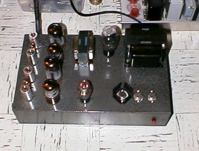
The above layout is one of the two finalists I arrived at, it is electrically and mechanically viable, but I eliminated it due to my concern over interchannel cross-talk inside the first driver tube. (Middle tube)
This is the actual topology I finally settled on, there were several other "non contenders" for the honors, but this seemed like a reasonable compromise and made good use of the cavernous internal chassis space.
These chassis are approximately 17" Wide x 10" Deep x 4" High. There is no point in building something like this on a tiny chassis, as the output transformers take up a lot of space. I recommend the chassis be fabricated of 16 gauge or 0.062" thick aluminum. Earlier amplifiers were built on copper chassis, the thickness of which was about 0.093". No internal stiffening is used so the material must bear the entire weight of the output transformers without bending.
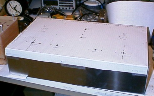
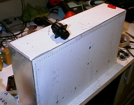
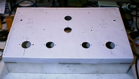
The previous three pictures show the creation of a template for cutting out the holes in the chassis. I used gridded paper as this made it very easy to assure symmetry across the top of the amplifier chassis. The important things here are to make sure that:
Tools I consider indispensable include a good set of Greenlee chassis punches or equivalent in the correct sizes for the sockets chosen, and a spring loaded center punch. Also needed are a good cordless drill, nibbling tools, reamer, deburing tool and an assortment of screw drivers.
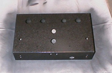
Here is what the painted chassis will look like, this is a view from the rear. Note that all the holes have been drilled, even those required for mounting the tube sockets to the chassis. I did this in order to reduce the likelihood of scratching the finish during construction. The finish was oven baked for about 2 hours and then allowed to cool for several hours. (Use caution, some paints may generate flammable/explosive outgassing during baking.) The finish has proved to be durable,
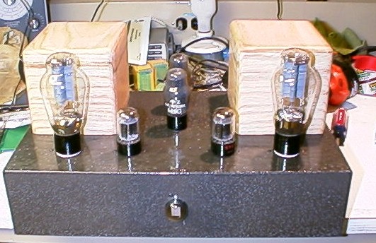
The little tube showing on the front panel is an ill-fated indicator tube which I will someday get working. For now the glow is decorative, but does give an indication that B+ is present in the amplifier.
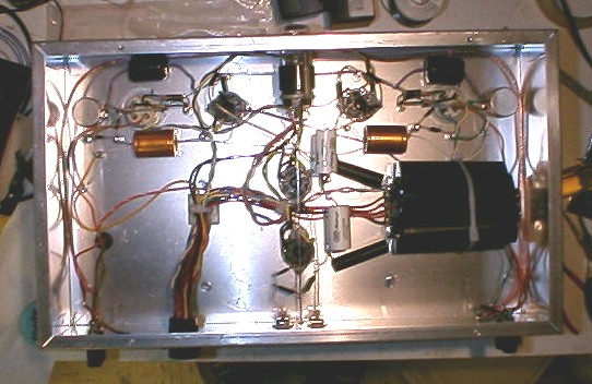
Here is an internal view of the chassis showing wiring details. The big lump of capacitors on the right are silver foil paper in oil power supply capacitors.
The Jensen and RTX foil caps shown in these pictures have been replaced with V-CAPS which are much more transparent than what they replaced incidentally.
You have probably noticed that the power supply has a lot more tubes in it than the actual amplifier. The third TO-3 regulator from the right is an LM317 which with a little "trick" provides the 1.8A required for the amplifier driver tube filaments. Note that a small heatsink has been added to this regulator. The two regulators to the right are used in the constant current supplies feeding the filaments of the 300B output tubes - one per channel.
Power supply operating....
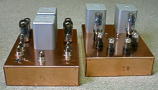
Here is one of the original amplifiers nearing completion, all that is missing are the front panels, which on this particular unit were engraved aluminum with the KTA and SOS logos. Note the use of custom Tamura power transformers along with the Tamura FS-5002 and WE300B output tubes.
Contact me if you would like to purchase the plans and schematics to build this amplifier. The purchase price of $50.00 buys you a PDF archive emailed directly to you, and includes unlimited support by email. (Available soon.) Payment by Paypal is accepted. Please note that this does not constitute an offer to build an amplifier for you, however if you can entertain a cost over 5 figures and wait several months or longer we may have something to talk about. :)
Note designs customized specifically to your needs are always available at higher cost.
This amplifier is heavily based on the design I used to manufacture for SOS in Nashua, N.H.
As always the information provided here is for personal use only, purchase of the documentation to build one of these amplifiers is for the purpose of building one unit for personal use only! No other use is permitted without the express consent of Kevin R. Kennedy, and without a written agreement in place.
![]()
![]()
© 2005, 2006 by Kevin Kennedy/KTA