I used a set of old Eico HF-81 pushpull output transformers, which when I measured the transformation ratio, and calculated the primary impedance turned out to be usable with a little subterfuge.. These transformers had a primary impedance of 7900 ohms referred to the 8 ohm secondary. I needed a trasnformer with half this impedance, and it just so happens that if you connect an 8 ohm load to the 16 ohm tap, the reflected impedance is 3900 ohms which is a reasonable load for a 45 running at +250V to +275V at 35mA or so. The same is true for a 4 ohm load connected to the 8 ohm tap.
You can employ any 6BQ5 output transformer this way as long as the primary impedance is close or somewhat higher. You can use the output transformer from the Dynaco SCA-35 integrated amplifier this way as well. This approach has the advantage that the inductance will be roughly twice that of a comparable transformer with 4000 ohm primary. Note that this sleazoid technique does have the disadvantage that the transformer will saturate more easily than one designed for single-ended service..
I chose to use an SRPP driver using a 6SL7 or 12SL7 to drive the 45 output tube, and chose to operate the 45 with 250V on the plate, at a plate current of 36mA which is close to the recommended values for operation into a 4K primary impedance. I tried slightly higher voltages and currents to a limit of +275V, but heard absolutely no improvement in performance, and consequently settled on the more conservative values cited for best tube life..
Construction Hints
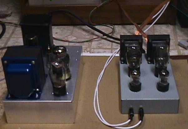
I built my amplifier as a stereo unit with outboard power supply unit. The chassis is a steel Hammond made unit 6" x 10" (15cm x 25cm), and the whole amplifier fits very
comfortably on it. I recommend the use of an aluminum chassis instead of the steel unit I used as this is much easier to work with... The power supply ought to fit on a slightly larger
sized chassis without difficulty..
I am using 12SL7* and plan to use well filtered and regulated dc to heat their filaments. There is no reason why 6SL7/6188 or 5691 could not also be employed as long as the filament
supply is adjusted for 6.3V operation. Currently I am using a bench supply to provide power to the amplifier while I design and build a power supply unit for it...
* I subsequently switched to 6SL7WGT upon completion of the power supply which has a 6.3Vdc filament supply.
The 45's filaments are heated using a precision center tapped 2.5V filament transformer with a 10A rating. Even though the unit is using AC to heat the 45's filaments there is no significant 60Hz hum on the output - not what I expected either! I am going to use AC heating in the outputs even when the power supply unit is completed..
Currently the +250V and -45V bias are provided by my Lambda bench supply, and the driver stage is supplied by another bench supply - Oh did I mention this amplifier uses fixed bias? Who needs large expensive cathode bypass caps and power resistors dissipating lots of power? Not me!!!! I tried cathode bias and the amplifier did not sound any better...
I am in the process of designing a regulated power supply using 6550 as the pass element to supply the 80mA required at +250V, the bias supply will be shunt regulated and adjustable to set the operating point of the output tubes. When it becomes available I will add the schematic to the zip file. Some of you may object to the use of a regulated supply, to which I say everyone has their preferences - seriously though you can get by quite adequately with a well filtered (choke pi filter), but you must make certain that the plate voltage NEVER exceeds 275V unless you like fire-works...
I used inexpensive carbon film** resistors from Radio Shack™, because I was looking for a vintage sound (doesn't sound vintage..) and SCR film/foil coupling caps. The grid stopper resistors are mounted close to the sockets
to prevent potential instability.. Star grounding was employed, and special consideration was given to keeping the 45's filament wiring away from the audio circuity..
All of the circuitry shares the 250V supply with decoupling provided for each channel. The currents listed in the schematic assume this fact, if you power the units separately the total current consumption per channel is about 38mA.
the bias supply can be made adjustable for each channel, and this may be advisable.. I plan to meter the B+ current, possibly for each channel, and make the bias independant for each channel. (Not as currently implemented...)
**Please see updates to understand why this particular gambit was a bad one..
The speakers used with this amplifier need to be very efficient, the Mission 763i I use in my lab are not really efficient enough at ~88dBspl @ 1 W/1M for good performance. Audible distortion can be heard on certain types of material even at modest levels..
Listening Results
The amplifiers can sound surprisingly good under the right conditions with the right material.. Bass quality is high, although not abundant, and not terribly deep as will be understood from the measured performance... The mid range is open and
warm, capturing some of the palpability that characterizes a good SE amplifier. High frequency performance is quite good as long as the power limitations of the amplifier are not exceeded. Plenty of depth, presence and speed. Its resolving power is quite
amazing. Sonically not quite what I expected in the sense that within its really limited power rating it manages to sound a lot like my non SE triode amplifiers. I think the output transformers are the really weak spot in this design, and eventually I will look for something
better to use... This amplifier sounds best with small acoustic ensembles, jazz or classical, material that is heavy on the bass end of the spectrum is a little light in heft, but with considerable articulation...
In general I am quite pleased with its performance, within the admittedly modest parameters I set for this design...
Update 5/25/98: The amplifier has actually at this point greatly exceeded my expectations sonically - with the latest updates it is extremely musical, and has a lot of resolving power. Surprisingly dynamic, with a lot of mid-range palpability, and clean detailed highs with no
hint of stridency. Sometimes the instruments actually seem to free themselves physically from the speaker system.. It has its own strengths which are not necessarily the same as those of a good pp amplifier, but in general any good amplifier should leave little of its own signature
on the music it reproduces, and I think in this respect the amplifier does quite well.
Design Revisions
I revised the amplifier design on 5/12/98 and was able to increase the maximum output power by over 30%, and in addition the amplifier sounds cleaner at lower volumes. The change basically consists of running the SRPP driver stage from a much higher rail than the 45's. The driver stage now operates at
340Vdc, and the peak swing into the 45 is now somewhat greater than 50Vpk (100Vpk-pk) - the limited swing is due to the fact that I used 100K grid resistors due to my discomfort with the possibility of grid current causing runaway. I will probably raise the grid resistors to 120K to decrease the load on the
srpp stage slightly. I think the amplifier sounds best with +250V on the plates of the 45's, at +275 it sounds a little strained..
Note: If you previously downloaded the schematic, you should replace it with this one...
Further Revisions - 5/17/98
I spent the last few days trying to extract better sound out of this amplifier, and I strongly recommend raising R5 to 120K ohms, and make no other changes - I tried a lot of things including raising R5 to 220K which measured slightly better, but sounded awful. I also tried adding about 3dB of loop feedback,
this resulted in a very slight reduction in distortion, slightly more bass, and a much flatter and more anemic sound quality. NOT RECOMMENDED!!! The power supply chassis is almost ready for wiring, when complete and reasonably debugged I will add it to the archive. This amplifier really needs efficient speakers
to sound good, otherwise you are tempted to crank it up to what seems like a reasonable volume and it is clipping frequently with a noticeable degradation in the sound quality.
Still Further Revisions - 5/25/98
After living with this amplifier for a while I came to the conclusion that it lacked clarity in the upper registers, this I initially attributed to the transformer finagle I performed in order to build these. Further investigation revealed this was not so! The high frequency smear I was hearing was due largely to
passive components in the power amplifier. I mentioned using carbon film resistors from Radio Shack to try to get some of that vintage sound - Didn't work and these parts in conjunction with the Nichicon cathode bypass capacitor in the SRPP stage were the culprits. I replaced the resistors in the SRPP stages with
Holco resistors, and the grid bias resistors with Resista's. The cathode bypass caps in the SRPP driver stages have been deleted with no ill effects. Coupling capacitors had previously been changed to RTX type with a little improvement over the SCR's I originally used.. The high frequency performance is now a lot better in keeping with the amplifier's
excellent mid-range, more detailed, much cleaner, and less soft/smeared sounding in the highs.. It is proving that this is a viable design inspite of the really low power output, on a lot of material you would never be aware of the amplifier's restricted power output...
Power Supply Design
I have designed and constructed a suitable power supply for this amplifier on a separate chassis, the high voltage driver, output and bias supplies are all regulated. Tube rectification is employed for the positive supplies, and the bias supply is designed to reach nominal output voltage in under 10 seconds, while the
plate supplies take about ~ 1 minute to reach operating voltage. The bias supply utilizes silicon rectifier diodes, and a zener in a low pass arrangement designed to eliminate line noise, ripple, and zener noise from the bias supply without requiring undue complexity, and the possible unreliability
this confers. The low level stages operate with their own high voltage supply of +320V and utilize an unregulated, but heavily filtered 6.3VDC supply. The 45's use 2.5VAC filament heating power, note that if you want to use DC filament power you should initially raise the
bias to -46VDC, and verfiy that the output stage plate current is around 33mA +/-5%.
The supply is designed specifically to power this and similar S.E. amplifiers, and will readily power an amplifier requiring up to 150mA if a KT88/90 pass tube is substituted for the 6550A. The design is optomized for low ripple & noise feed-thru, and reasonably tight line/load regulation. Ultimate voltage accuracy is not extremely critical - hence no provisions have been made to adjust any of the output voltages. I recommend tightly specified 1W 5% zeners measured at 1 - 3mA, if voltage is within +/-2.5% of nominal 100V over this whole range, performance will be excellent. Note that the use of this power supply resulted in a stunning improvement in the overall sonics of this amplifier - it now sounds much cleaner, more powerful, and more detailed..
Measured Electrical Performance
The measured performance is quite horrible actually - perhaps even worse than most SE designs, except in the area of noise and bandwidth which are quite reasonable for a 0 fdbk amplifier..
Revised: 5/15/98
Frequency Response at 100mW:
30Hz - 30KHz @ -3dB
60Hz - 20KHz @ -1dB
Voltage Gain:
+9.0dB @ 1KHz
THD:
0.4% @ 1KHz and 100mWrms
4.0% @ 1KHz and 1.6Wrms
Other Comments
This thing is actually cute to look at, and is quite diminutive in size. Great for a
very small system... I used used 45's which I got for about $10.00 apiece. One of the
tubes exhibited suspicious behavior in terms of its sonics, so I replaced it -
can't decide if this actually helped or not.. I built this thing in under 4 hours - when
was the last time anyone built an entire stereo amplifier from scratch in such a short time period?
Update 9.13.98: I just purchased a good set of used RCA Radiotron UX245 globes, boy do they
sound great! Even better than the somewhat newer ST types. If you can afford these they are definitely
the way to go, and oh so cool looking... I use this amplifier everyday in my shop, and love it! I have had
some problems with that 0.1uF capacitor (C1) shorting out! I recommend using four 0.1uF/1KV caps in series
parallel in order to get the required capacitance if you are also having this problem. Add a 470 1W resistor
in series with the caps to define a minimum high frequency impedance for transient protection.
If you are using C4 in the amplifier section this part should be deleted - it just sounds better without it..
Update 10.07.03: I am still using this amplifier with the afore mentioned UX245 globes and this amplifier has risen to
the status of being my favorite project amplifier of all those I have designed.. My cheap introduction to SE has become the mainstay
of my system and I use it to drive a pair of JBL Rhodes C37's.
Update 11.27.05:I recently gave this amplifier to one of my close friends after years of faithful and troublefree service. It
has been replaced by a much more powerful 300B SE amplifier based on one of my last commercial offerings. It is still without a doubt
one of the best amplifiers I have ever done.
You know that the fixed bias supply could readily be replaced with a 45V battery (essentially 5 series connected 9V batteries) and a diode string to
drop the voltage a couple of volts - biased by few tens of uA of current through a 1 - 2 M ohm resistor or better still two series connected AAA penlight batteries wired
in reverse to buck the -45V down to -42V. Just a thought.. Battery life would be years at least..
KRK 11/27/2005