So far I have had a cathode follower tube which I believe failed due to a defective 6C33 output tube which had several visible hot spots on the cathode
surface. The speaker line is fused as well as one of the floating B+ supplies in order to protect the speaker and if fortunate perhaps the output tubes
as well, when these types of faults occur.
I am now succcessfully operating the amplifiers with all six output tubes installed, and have not seen any bias or offset instability worth mentioning, however I have observed that it takes about 15 minutes for the tubes to reach full emission, and therefore the final bias adjustment should not be performed until this time.
Russian quality control leaves a lot to be desired, of the 17 tubes I purchased 2 are clearly defective, (12% failure rate) one previously cited in update4, and the other newly discovered with a warped grid support structure in one section - although this one works some bias drift was evident with it installed in one of the amplifiers, and I was concerned that it would eventually develop a grid to cathode short and make a nasty noise, and ruin another 12SN7... The remaining 6C33 seem to be performing well, and offset and bias points are stable after warm up, performance in this regard seems to improve as the tubes age slightly. I have not yet matched the tubes so to prevent problems I am running them at around 200mA each, and after I match them reasonably well I plan to increase the idle current to roughly 300mA each for even better linearity.
The sound is getting close to what I would expect from these amplifiers, although I am not yet using them in my main system, the workshop system is not bad at all.. I am hearing things with these amplifiers that I never heard on these speakers before (Mission 763i), and the bass extension is beyond incredible.... They sound quick on percussive instruments in a way I have not really heard before in a tube amplifier. Treble is much improved as well, in terms of extension and quality.... I also still hear that darned 120Hz buzz when no music is playing - next thing to fix....
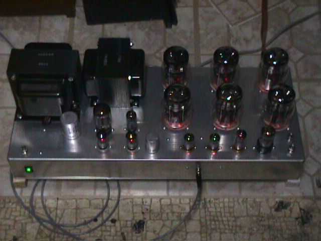
These amplifiers also make excellent room heaters - even runing at 2/3 intended idle dissipation they consume about 1/2KW each and just about all of this is wasted as heat. I don't plan to use these extensively during the summer months if they heat up my basement listening room the way they heat up my lab... They also are quite impressive looking to the initiated as well as the unitiated....
Eventually the plan is to use these to drive my MG1.4's, which are essentially a 5 ohm resistive load. Unfortunately OTL output power goes way down as the load impedance decreases. These amplifiers produce approx 130W into 5 ohms, close to 300W into an 8 ohm load, and a theoretically unbelievable amount into 16 ohms... Running these sorts of tests on OTL output stages seriously threatens the output tube life so I won't being doing any more testing at these power levels....
Mis-haps continue to plague the project, I discovered to my chagrin that the IR drop across the line to my shop was sufficient to keep the amplifiers happy during inrush and early warm up, however the listening room has very short direct feeds from the main entrance panel, and the amplifier ac line fuses blew instantly, and when replaced I discovered that the + series pass raw supply was 50Vdc higher than the cap rating which proceeded to cause further problems with fried fusing resistors in the high voltage supply....Inspite of these problems they did run reliably for about 10 hours over the week-end.
Did I mention they sound great, (when they are working) actually I am really beginning to understand the sonic allure of this technology.. Lots of detail, speed, unbelievable bass - tightly controlled, and neutrality of an order I have not previously experienced listening at home..
A full month has passed since the last update, but plenty has been happening as I work out the kinks in the design. Fundamentally these amplifiers perform best when driven differentially (balanced) - an overly optomistic viewpoint on my part made it appear as though internal balance in the driver circuitry would not be a problem even with SE drive, but it turns out that best overall balance was achieved with 0 applied loop feedback... Poor sonic performance with the desired closed loop gain of 32dB forced serious bench evaluation. The gain reduction brought about as a result of loop feedback application was all occuring in the negative leg of the driver stages! (It actually swamped the desired differential output signal and produced a common mode output signal differing only in amplitude by -6dB/not phase!! to the output stage.) This seriously reduced the available drive voltage to the output stage, reducing the available output power, and the output stage insertion loss was nearly 6dB under worst case (highest feedback) conditions. I will have to remeasure the drive stage performance to ascertain that the available drive is adequate, now that the amplifiers have been modified for balanced inputs...
Interestingly the amplifier sounds very good without any feedback applied, hum however due to ripple on the floating supplies is quite audible with no music playing. Chokes or 120Hz traps in the floating supplies would probably solve this problem. In my case 10dB of loop feedback takes care of the problem handily, as well as assuring flat frequency response into real world loads...
The fan cooling is now operational in both amplifiers and keeps the chassis' cool over long hours of operation. Forced convection was the only way to go here due to the limited space, and a unbridled desire that the expensive components in these amplifiers live for a while. The fans are a little noisy when new, but quiet down after a few hours of operation. The 12Vdc power supply arrangement used to power them is a crude stop-gap measure, and I intend to improve them - perhaps even add temperature dependant variable speed control.
As I mentioned earlier I am now driving the amplifiers with balanced drive, I chose to use T3F and T3M connectors for cables and I/O due to their small size and similarity to their larger XLR brothers... All this means is that I also had to design, build and debug a pre-amplifier to do this. The pre-amplifier features a cross-coupled differential amplifier identical to my 6CK4 amplifier which drives a 5814 based dual cathode follower.. Relays are used for muting, polarity, and source select. Most relays seem to be lousy muting devices - even milli-ohms of contact resistance makes for less than exemplary muting performance, but I hate to add series resistors to improve the attenuation because it raises the output impedance of the pre-amplifier..
I am not satisfied that I am there yet in terms of extracting maximum performance from either the amplifiers or their new cousin - the balanced pre-amplifier. Inspite of the reservation the amplifiers exhibit great detail, excellent bass control, slam, depth, ambience retrieval, a certain palpability and presence, and balanced timbre. Better yet they have run for at least 30 hours without failure, and with only minor bias, common mode and diff. mode offset adjustments. The speakers may be safely left connected during power up and down sequences, making them practical for everyday use. It is very doubtful that I will ever go back to my conventional amplifiers once all the new electronics are complete, and debugged. (I need a new phono stage now as well.)